|
The OC-Melbourne Home Entertainment PC (HEPC) Mod
Construction Process
Firstly I'd just like to apologise for a lack of construction images. This
was my fault, as I had them stored on an IBM Deskstar 60GXP which, with utterly
terrible timing, decided to fail, taking my entire mp3 collection (legal of
course) and all my web content with it. I know I'm probably going to be flamed
for not backing up the images, and I suppose I deserve it. Unfortunately, the
box is so restrictive in size, that it had to be put together in a certain process,
and reversing this process is not possible, without possibly damaging a couple
of pieces of hardware, so I cannot take it apart and get some more photos other
than what are shown here and on the next page in the image gallery.
Step 1 - Readying the Case
Before we could even begin putting the box together, we had to remove the existing
VCR hardware from the case. This was probably the best part of the whole process,
as we got to smash and bash as much of the old hardware as we felt like.
Step 2 - The Custom Motherboard Tray
In order to be able to mount the motherboard to the case, we had to construct
a custom motherboard mounting tray. We could have mounted it to the actual chassis
itself, but this is only plastic, and we didn't want any screws sticking out
the bottom of the case. Inside the case, however, was not entirely flat. We
had small stands where the existing hardware used to sit on, and around the
sides we had many little clips which got in the way of where the motherboard
was to sit. How did we solve this? A hacksaw!!
After removing all the extruding plastic, we still had some small pieces around
the sides of the case that if removed, could cause a problem to the cases structure/stability,
hence they were left there. Working with these extrusions, we created a custom
motherboard tray out of perspex.
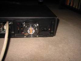
Step 3 - The Power Supply
The power supply (PSU) was one of the hardest pieces of hardware to fit into
the case (apart from the HDD which we will talk about next). We needed to do
a number of things before the PSU was fitted into the case. Firstly, we needed
to cut a hole in the back of the case for the PSU power socket to fit into.
Secondly we needed to cut a hold for a fan to be mounted on the back of the
case, as we had removed the stock cooling fan from the unit in order to save
space. Finally, before we could mount the PSU, we needed to cut the back casing
of the PSU in half, so that the DVD drive could fit into the case. It was worrying
at first to see the metal dvd drive so close to the exposed workings of the
power supply, but a bit of grounding wire later, and all concerns were eased.
The images below show just how daunting a task fitting this PSU into the case
was. It was affixed to the case using the 4 fan mounting screws and one custom
screw hole to the left of the PSU power socket. Notice the plastic cover on
top of the PSU. This was actually added AFTER the entire project was completed
after a certain someone (me) decided to be smart and put his finger on the heatsink
in the PSU to see if it was hot, without removing the mains power beforehand.
Suffice to say, I wont be doing that again.
Step 4 - The Hard Drive
This was easily the most time consuming pert of the whole project. In order
to mount the hard drive (HDD located under the DVD drive), we had to make a
custom mounting bracket. This was done using an old 3.5in HDD mounting rack
from an old IBM 486 machine. It originally had room for 4 hard drives, but we
had to modify it so it only had room for one, as well as making some custom
mounting holes to mount it to the bottom of the case. In order to do this, our
trusty angle grinder was used, since I don't own a dremel. A few cans of coke
and an hour later, I had the perfect mounting device for the hard drive. (Sorry
again that I don't have any images of this, but it is EXTREMELY hard to get
to the hard drive without damaging the DVD-Drive).
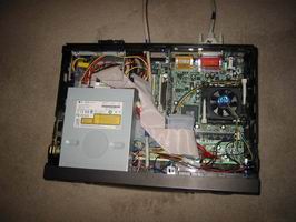
Step 5 - Mounting the Motherboard
This was a fairly easy task, since all it required was drilling a few holes
in the perspex motherboard tray, then using a couple of self tapping screws
to secure the motherboard to the tray. Rubber spacers were used to give a little
clearance from the tray for all the solder points under the motherboard.
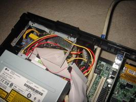
Step 6 - Mounting the DVD Drive
This was also a fairly easy task, however it did require using something a bit
out of the ordinary when it comes to mounting DVD drives in cases. We used a
bracket that is used to mound 3.5" devices into 5.25" bays. We can
see this bracket on the left in the image below.
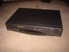
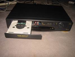
Step 7 - Attaching the Drive Bay Cover
For a little added aesthetic pleasure, the DVD drive was placed behind the existing
"VCR Flap" where VCR's used to be loaded. We removed this flap from
the case, and modified it so that it wouldn't catch on the casing, then mounted
it to the front of the DVD drive using double sided car body molding tape (strong!!).
We can see in the images below how it looks when the drive tray is in, and when
the drive tray is out.
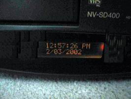
Step 8 - Mounting the LCD
This part was relatively easy, we simply removed the existing LCD display and
replaced it with the Crystal Fontz 16x2 LCD. We affixed the LCD using hot glue,
which holds the LCD perfectly in place. The data cable for the LCD unfortunately
has to travel right through the case and plug into the rear parallel port, but
hopefully in the future we can use some form of internal connection. The LCD
can be seen in the image below.
Step 9 - Final Touches
In order to make this device seem more like a real VCR, we wired the existing
power and eject buttons (previously used to turn the VCR on/off and eject the
tape) to control the system power, and eject the CD/DVDROM tray. This required
pulling the DVD drive apart, and soldering 2 wires onto the eject button terminals,
then wiring this to the eject button in the front of the case. The Power button
was easier as it simply needed to be connected to the switch in the front of
the case, then plugged onto the motherboard "Power Switch" header.
These buttons can be seen below the VCR flap in the picture below.
Now for what you've all been waiting for, the image gallery!!
<< Prev - Hardware Specifications || Next
- Image Gallery >>
|